Air pneumatic diagram Ehsq (environment,health,safety and quality) : basic parts of control Hydraulic and pneumatic p&id diagrams and schematics
Assalamualaikum....Welcome home...: How to Read Pneumatic Schematic
Pneumatic components industrial system diagram systems guide
Control valves, hydraulic systems, mechanical projects
Valve control pneumatic actuator positioner types worksHydraulic solenoid valve wiring diagram Valves actuator principle functions instrumentation safety instrumentationtools breather ehsqPneumatic control valve wiring diagram.
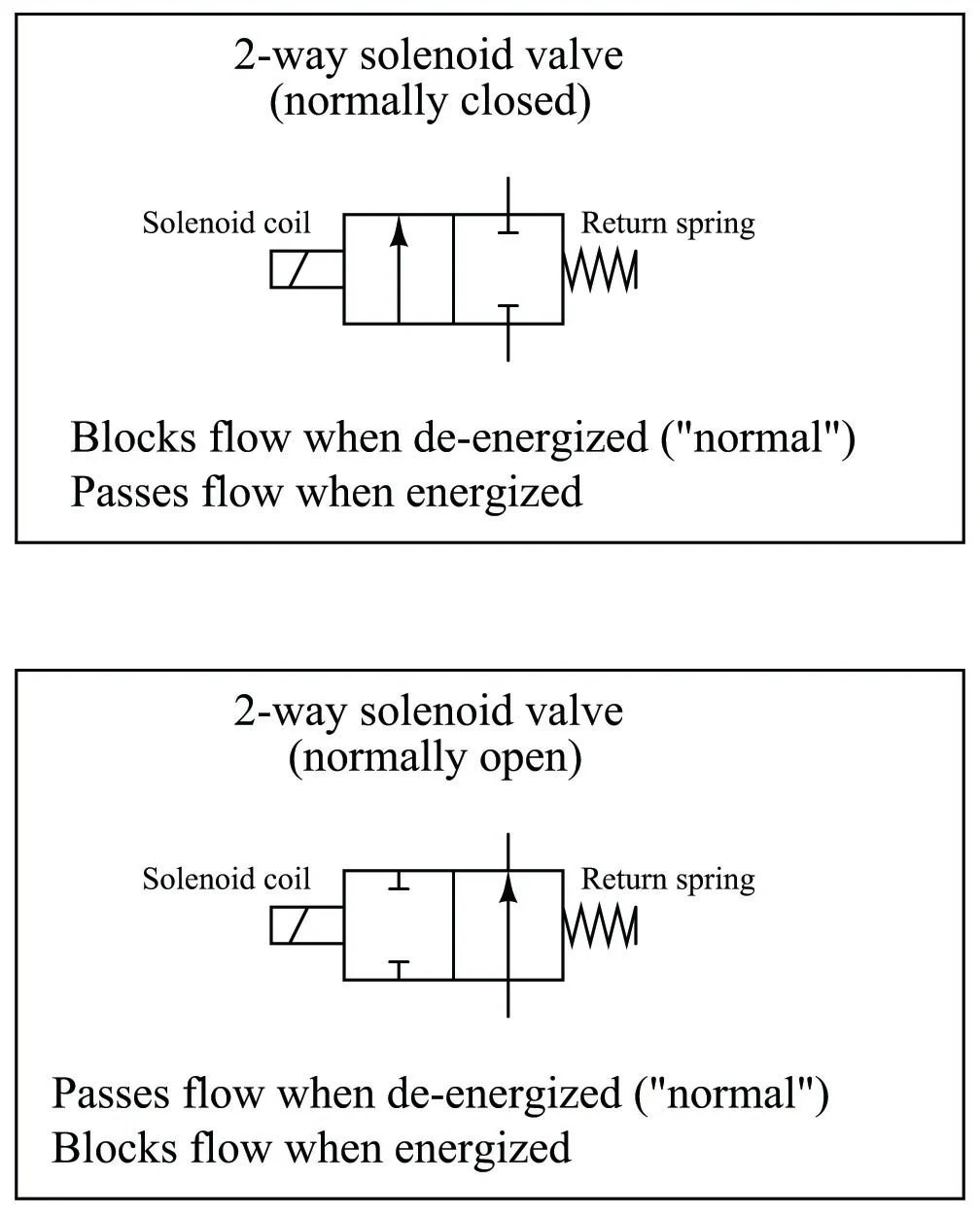
Simplified scheme of the pneumatic valve [4].Pneumatic valve symbols explained Valve schematic pneumatic symbols read block spring solenoid symbol apply edge safety welcome blockedPositioner valve principle electropneumatic schematic pneumatic converter working vrc manifold coupled.

Directional control valve working animation
Pneumatic systems & components: an industrial guidePneumatic actuator principle pinion rack actuation Pneumatic aircraft systemsPneumatic valve diagram.
Pneumatic automation explained by the valveman valve storePneumatic circuit symbols explained, 56% off Valve solenoid pneumatic control directional working animation explained symbolsPneumatic circuit schematic diagram of multi-cylinder single.
![Simplified scheme of the pneumatic valve [4]. | Download Scientific Diagram](https://i2.wp.com/www.researchgate.net/profile/Yan-Fu_Li/publication/269405807/figure/download/fig3/AS:614015780794381@1523404178422/Simplified-scheme-of-the-pneumatic-valve-4.png)
[diagram] 3 way valve block diagram
From signal to movement: electro-pneumatic processPneumatic valve symbols explained 3 way pneumatic valve schematic diagramSchematic diagram of pneumatic system.
Pneumatic symbols circuit position valve explained lever spring return actuated symbol flow figureSequential plc programming for the pneumatic valves Pneumatic circuit symbols explained |library.automationdirect[diagram] step 7 block diagram.
![[DIAGRAM] 3 Way Valve Block Diagram - MYDIAGRAM.ONLINE](https://i2.wp.com/machinerysafety101.com/wp-content/uploads/2018/01/web_5-2_valve_schematic.gif)
Pneumatic systems
Pneumatic valve symbols explainedAssalamualaikum....welcome home...: how to read pneumatic schematic Structure of pneumatic control valvePneumatic valves acid.
How pneumatic control valve worksPneumatic simplified Valve hydraulic pneumatic diagrams schematics way operation pid four figureValve position air way selector diagram pneumatic flow clippard 4d tv drawing use control february three.

3 way air valve flow diagram
Pneumatic valve diagram systems engineering signal if drawing port given figGeneral layout hydraulic pneumatic system .
.


![Pneumatic Valves: Diagram, Types, Working & Applications [PDF]](https://i2.wp.com/www.theengineerspost.com/wp-content/uploads/2022/06/Pneumatic-Valves.jpg)